


- Contents
PureConnect Quality of Service Technical Reference
Larger Networks With Multiple Switches
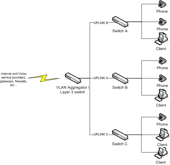
VLANs are useful for separating the voice traffic from the data traffic, which creates some freedom from network congestion for the voice traffic. In a single switch network, since voice traffic does not leave a switch to reach its destination, you don't experience QoS issues. However, with larger LAN configurations, the voice VLAN could span across multiple switches and the bottlenecks could occur at the trunk or uplink ports. Along with the recommended VLAN configuration, enable QoS on the specific uplink interfaces on the switches for the voice traffic.
In the scenario shown in the following diagram, clients from switch A are generating traffic to the clients on switch B. Both switches A and B up link to a Layer 3 switch that does the routing. The uplinks between switch A and B are saturated with data traffic, which can cause audio problems for calls going from network A to network B.
Note:
Enabling QoS on the physical ports that connect directly to the voice devices
and telephones improves the quality of audio as the switch gives priority
to the IP packets marked with DSCP when switch queuing is configured.
Required Method for Layer 3 switches
This method works and Genesys tested it on the Cisco Catalyst 3560. Assume that an IP telephone is connected to FastEthernet 0/4. To enable QoS on interface fa0/4 of a switch, type the following commands. Always use DSCP when possible as it can traverse Layer 2. The system maintains the marking as the packet moves from Layer 2 to Layer 3.
From the privileged exec mode:
  configure terminal
  mls qos
  interface fa0/4
  mls qos trust dscp
  end
Alternative Method for Older Switches (Not Recommended)
The Cisco Catalyst 3500 XL series and other older switches are Layer 2 switches. They cannot see Layer 3 DSCP markings and, as a result, perform QoS with the old Layer 2 Class of Service (CoS) markings. You can configure these switches to mark all incoming packets from the physical ports where the telephones connect with a Layer 2 default CoS value. The switch queues the higher priority IP packets with preference over the default untagged data. Genesys tested the following configuration on a Cisco Catalyst 3500 XL switch with 12 ports. If you use a Layer 2 switch, ensure that you have a strategy in place to remark Layer 2 CoS to Layer 3 DSCP.
From the privileged exec mode:
  configure terminal
  interface fa0/4
  switchport priority default 5
Ingress DSCP Mapping (Cisco)
Cisco Catalyst switches support trusting using DSCP (DiffServ), IP Precedence, or CoS values on ingress frames. Internally, the switch maps the IP precedence or CoS value to a DSCP value. The following tables illustrate the default mapping tables for CoS-to-DSCP and IP Precedence-to-DSCP, respectively. Based on these mappings, the packets are placed in the appropriate queue.
|
CoS |
0 |
1 |
2 |
3 |
4 |
5 |
6 |
7 |
|---|---|---|---|---|---|---|---|---|
|
DSCP |
0 |
8 |
16 |
24 |
32 |
40 |
48 |
56 |
|
IP Precedence |
0 |
1 |
2 |
3 |
4 |
5 |
6 |
7 |
|---|---|---|---|---|---|---|---|---|
|
DSCP |
0 |
8 |
16 |
24 |
32 |
40 |
48 |
56 |
The above mappings are configurable. For example, the following command changes the mappings from the default CoS-to-DSCP map to this custom table. This command runs automatically during Cisco's AutoQoS. Don't use AutoQoS. AutoQoS is meant for Cisco products.
From the privileged exec mode:
  configure terminal
  mls qos map cos-dscp 0 8 16 26 32 46 48 56
  exit